Contents:
- Techniques for Wide Angle Panoramic Photography
- Techniques for Wide Angle Panoramic Eclipse Photography
- Panoramic Eclipse Photography; Challenges:
- Analysis of Wide Angle Eclipse Photography Techniques & Challenges
- Conclusions
| Techniques for Wide Angle Panoramic Photography. Introduction © Copyright 1986, 1987, 1991, 1997, Jeffrey R. Charles, All Rights Reserved. |
||
A number of techniques can be employed in 360 degree panoramic photography:
|
||
 |
 |
|
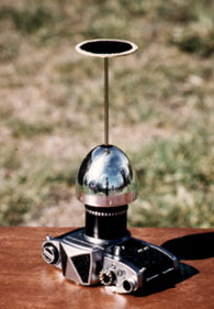
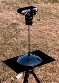
| 320 degree wide angle reflector which I built in 1977. It uses a L'eggs hose egg for the reflector. The camera lens is behind the small hole in the center of the reflector. The flat mirror at the top of the axial support strut allows the camera to "see" a reflection of the L'eggs reflector. I patented a version of this design which uses a better reflector. (U.S. patent No. D312,263). | All sky reflector with axial camera support which I built in 1985. The reflector is a common hubcap. The angle of view is about 190 degrees. Other reflectors can offer a greater angular coverage. Because the reflector is large, this system can be used at f/ratios as fast as f/2. An improvement of this version is also covered in my patent. | |
| These wide angle reflector designs are covered more thoroughly in my article entitled "All Sky Reflector with "Invisible" Camera Support". | ||
 |
 |
|
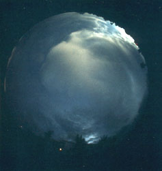
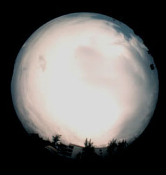
| All sky fisheye shot taken during totality at the 11 July 1991 solar eclipse. North is on the bottom and east is on the right. The exposure is 1 second at f/5.6 on Kodachrome 64. | All sky fisheye shot taken two minutes after the end of totality. Note the obvious darkening on the horizon toward the east and southeast. The exposure is 1/4 second at f/5.6. | |
 |
||
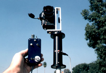
| This automated remote control motorized indexing rotary camera platform was designed to take a series of photos at total solar eclipses and other time critical events. When "spliced" together, the photos make up 360 degree panoramas. The platform can be configured to stop at various predetermined intervals in order to accommodate the optimum use of different camera lenses. The hand control includes interval timers for automated operation of both the camera and platform. | ||
 |
||
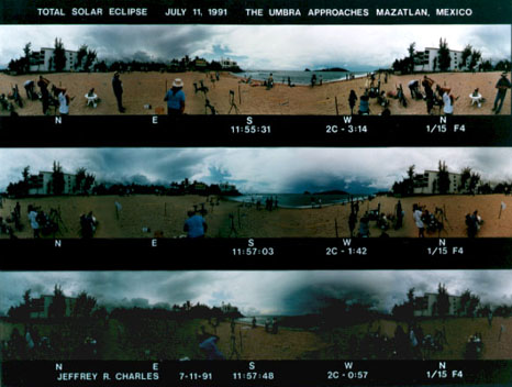
| The indexing rotary camera platform shown above was used to take these 360 degree panoramas of the lunar umbra approaching Mazatlan, Mexico at the 11 July 1991 Total Solar Eclipse. Each panorama is made up of a series of four photos which were taken with a 16 mm fisheye lens. | ||
 |
||
| Even ordinary subjects can appear unusual when photographed with an extremely wide angle lens. This is my cat, Moses. | ||
Selecting The Best Techniques For Wide Angle Eclipse Photography.
© Copyright 1986, 1987, 1991, 1997, Jeffrey R. Charles, All Rights Reserved.
Of the wide angle photography methods discussed above, only a few will work well for terrestrial photography at a total solar eclipse. A total solar eclipse presents unique challenges which drive the requirements for applicable instrumentation. If high resolution is required, only the "spliced"series of wide angle photos will work really well, as discussed below.
Panoramic Eclipse Photography; Challenges:
- The light level changes rapidly near the time of totality.
- The ambient light is very subdued during totality.
- The umbra moves relatively fast.
- A wide vertical coverage is desirable for umbral images.
- High resolution is required if enlarged sections of the image are to be acceptably sharp.
- Eclipse sites can be remote; therefore, eclipse equipment should be portable (and easy to set up).
Analysis of Panoramic Eclipse Photography Challenges:
The light level changes rapidly near the time of totality. Within a minute or so of totality, the ambient light level can change at a rate of more than three f/stops per minute. This change can be compensated for manually with most cameras. Automatic compensation is only recommended if an incident light meter is used for the sensor. A reflective meter can be "fooled" depending on its orientation to the umbra.
Using Rotating Slit Cameras During Totality
The ambient light is very subdued during totality. A typical exposure with ISO 100 film is about 1 second at f/4, though exposures as long as 3 seconds at f/4 may be appropriate at some eclipses. In addition, the visible boundary of the umbra moves relatively fast. These factors make the use of a rotating slit or line scan camera very impractical for obtaining horizontal panoramas, since such a camera would require a long time to make a complete circuit of the horizon. During this time, the umbra may move significantly and appear distorted in the resulting image. Even worse, the camera may fail to complete a properly exposed panorama (or the required number of panoramas) during the brief moments of totality. It is also difficult to even find a rotating panoramic camera that is capable of taking long exposures. The subdued light also causes a problem for most motion picture cameras.
In order to produce a sharp panoramic image with a rotating camera, each point in the image must move in a straight line and at a constant rate across the camera slit. Accordingly, increasing exposure time by widening the slit in a rotating camera is not practical if wide vertical coverage is required. This slit width limitation is caused by the off-axis imaging characteristics of extremely wide angle lenses. These characteristics are briefly described below.
Fisheye Lenses
Fisheye lenses have projection characteristics which radially compress the image proportions toward the edge of the field of view. As a result, straight lines which are imaged non radially or off-axis will appear as arcs which have their centers toward or beyond the center of the picture. The farther from the center of the lens a line is imaged, the more strongly it will be curved. This effect will cause a square object at the center of the picture to appear bloated. Compared to other lenses, a fisheye lens can be said to have "barrel distortion". When a fisheye lens is used on a rotating camera having a wide slit, the image can appear sharp along the horizon but its horizontal resolution gets increasingly worse toward the top and bottom of the picture. This problem is easy to envision when you consider that the point directly above or below the camera would have to be imaged as a streak which extends the full width of the panorama!
Rectilinear Lenses
Most wide angle lenses utilize what is called a rectilinear projection. This is the same projection that would be imaged with a pinhole camera, and it images straight lines as straight lines in the picture, regardless of their orientation to the lens. If a rectilinear lens is positioned above the exact center of a flat subject but is not pointed squarely at it, the image of the subject will be distorted, or "keystoned", with the part of the subject farthest from the center of the picture appearing to be enlarged. This is desirable for wide angle photography of some subjects, because it tends to exaggerate perspective. A rectilinear lens is also incapable of covering an angle greater than or equal to 180 degrees. This is easy to envision when you consider the pinhole camera. Fortunately, the rotation of the panoramic camera will cover the 360 degree horizon. The lens only limits the vertical angle covered by the panorama.
When an extremely wide rectilinear lens on a rotating panoramic camera, the resulting image will have normal proportions near the vertical center, or "equator" of the panorama, but it will have vertically enlarged images of items toward the top or bottom of the panorama. This can cause a 360 degree panorama with only 115 degrees vertical coverage to have an an aspect ratio of only 2:1, making it appear more like an ordinary picture than a panorama. In this case, the vertical proportions of items near the top and bottom of the panorama will be exaggerated nearly two times.
Panoramic image sharpness with a rectilinear lens: When an extremely wide rectilinear lens is used to expose film through a slit in a panoramic camera, the image appears sharp along the horizon, but in this case, the vertical resolution gets increasingly worse toward the top and bottom of the picture. This problem arises because the image scale of a rectilinear lens increases toward the edge of its coverage. The change in image scale is directly proportional to the change in linear distance between the secondary principal point of the lens and the relevant imaging points on the film plane.
The smearing is caused by the difference in vertical image scale imaged by the lens at vertically off-axis points between the horizontal center and edge of the slit. This change in image scale causes the position of vertically off-axis points in the image to be shifted during the exposure. The cumulative change in vertical image scale (and the resulting change in off-axis imaging position) is is directly proportional to the change in linear distance between the secondary principal point of the lens system and relevant points along the horizontal axis of the sensor plane. This change is often larger then the absolute change in local image scale. With an ultra wide lens, this change in vertical image scale is enough to vertically shift the imaging point for a given subject even when the image only moves across a relatively narrow panoramic camera slit. Such a change in the imaging point during the exposure will obviously cause the final image to be smeared!
The off-axis enlargement of the image is responsible for the above mentioned "keystone" effect one can see when a rectilinear lens is not pointed squarely at a flat subject. The very fact that an image does "keystone" depending on the orientation of the lens makes it obvious to see why smearing would result if a wide slit is used; a line segment which appears to tilt as the lens/camera combination is panned obviously will not be imaged sharply. When the image of a point near the vertical limit of coverage moves from the center to the edge of a wide slit opening, it moves in an arc toward the edge of the film, resulting in a smeared off-axis image. This effect is negligible with narrow slits and lenses having less than about 50 degrees of vertical coverage, but it can be a problem with wider lenses. Even so, the off-axis image is not degraded nearly as much as it would be with a fisheye lens, so rectilinear lenses are typically the type used on rotating slit cameras. In light of the above factors, rotating cameras with wide slits may not work well if both high resolution and a wide vertical coverage are required.
Even though off-axis image smear with a rectilinear lens is not as bad as with a fisheye, it is still a problem for extremely wide coverage. For example: One rotating 360 degree panoramic camera I designed used a 14 mm rectilinear Sigma lens and 120, 220, or 70 mm film. The vertical coverage of the lens (and the resulting panorama) is 114 degrees. In order to allow a marginally acceptable shutter speed of 1/4 second with a 5 second rotation time, the camera slit was 5 mm wide. Even with such a modest slit, the top and bottom limits of a panorama taken with a 14 mm lens would be smeared nearly 0.4 mm! This significant vertical smearing corresponds to an angle of about about one degree in the resulting picture. With a 1.2 mm wide slit, the edge of the image would only be smeared about 0.05 mm, but the camera would take four times longer to complete its rotation for a given shutter speed. This limitation obviously dampened my enthusiasm for building this camera for use at eclipses. My estimate of 400 man hours to build a prototype did not help either!
Electronic Imaging With Rotating Cameras
In spite of the shortcomings rotating cameras have for film photography in subdued light, there is hope for the rotating camera concept when it comes to electronic imaging. For use in dim light, such a camera would have to use a rectangular sensor array rather than a simple linear one. This would result in the same image smearing that is associated with slit cameras were it not for the fact that some sensor arrays can be made to compensate for the problem. Since the off-axis characteristics of various ultra wide lenses can be calculated, the image can be properly mapped and processed as it moves over a rectangular sensor array as the picture is taken. As the image moves across the sensor array in a progressive exposure, the information from the first column of pixels is transferred to the next column, where the exposure continues. This progressive exposure approach has the potential to result in a cleaner image than would summing together hundreds of short exposures after the fact.
To eliminate blurring with a rectilinear lens during a progressive exposure, information from vertically off-axis pixels is simply reassigned to new pixels with appropriate off-axis positions as the information is progressively transferred to each column. This should make it possible to completely eliminate blurring even when a wide sensor array is used. The degree of image smear is more or less linear as a function of the vertical off-axis distance, so the algorithms to compensate for it can be fairly simple. Minimizing blur with a fisheye lens would be much more difficult, but still possible. Dynamically processing the image by changing vertical pixel assignments as the picture is taken would be an expensive proposition to start with, but it should gradually become more affordable as it is applied to other disciplines.
A brief analysis of one example follows. This example will be for a point which is imaged is imaged a 22 mm off-axis by a 14 mm rectilinear lens. The sensor area considered is 5 mm wide and 44 mm high, though a wider or narrower sensor could obviously be used.
Compared to how it will be at the center of the sensor, the image is vertically expanded as it first moves onto the side of the sensor. As the image moves horizontally toward the center of the sensor, it will shrink vertically. As the image continues to move toward the opposite side of the sensor, it will expand again. This will cause a point in the image which is near the top or bottom of the sensor array to describe an arc as it moves across. At the limits of vertical coverage, the arc starts on the edge of the sensor, moves slightly toward the center of the sensor, then moves back to the edge again, as shown in a highly exaggerated form on the front view of a sensor below:
XXXXXXXXX X = Boundary of sensor.
Xo-----oX o = Path of imaged point across TOP of sensor
X-o---o-X
X--ooo--X
X-------X
Xoooooo>X o = Path of imaged point across CENTER of sensor
X-------X
X--ooo--X                            <--I
X-o---o-X                               I bracket = image smear
Xo-----oX o = Path of imaged point   <--I
XXXXXXXXX     across BOTTOM of sensor.
The degree to which the imaged point moves toward and away from the vertical center of the sensor is a function of the angle of the lens, the vertical off-axis distance, and the width of the sensor. The effect can be compensated for by adding and subtracting the appropriate proportion of pixels in each column of the sensor as the image moves across the sensor.
Calculations relating to compensation for image smear are shown below. The examples will be for the same 22 mm off-axis point which is imaged with a 14 mm lens on a 5 mm wide sensor array. Since the motion of the imaged point is symmetrical on any quadrant of the sensor, the equations need only deal with one side, or 2.5 mm of the sensor. The change in vertical image scale is directly proportional to the change in linear distance between the secondary principal point of the lens system and relevant points along the horizontal axis of the sensor plane, so the problem can be graphically represented in a top view of the lens and sensor. An arc having a radius equal to the focal length of the lens system is drawn about the secondary principal point. Since the effective focal length of the lens system is equal to the distance between the secondary principal point and the axial focal point, the center of the sensor is tangent with this arc:
X = Secondary Principal Point


-------o = Arc
-----o
ooooxxxx = Sensor Plane
A more complex way to visualize the problem is to consider two widely diverging lines in the same vertical plane which intersect at the center of a pinhole that is 14 mm in front of the sensor. Outside the camera, the ends of these lines touch fixed points on the subject which are near the top and bottom limits of coverage on the sensor. Now visualize horizontally rotating the pinhole and sensor combination about the center of the pinhole, but leaving the intersecting lines where they are; still extending from the same points on the subject and through the pinhole. Obviously, the angle between the intersecting lines will remain constant as the camera is rotated because the distance between the pinhole and subject will remain constant.
Now consider the same lines as they diverge behind the pinhole. As the camera rotates, the angle between the lines remains constant, but as their relative rotation moves them across the sensor, (and in this case, away from the horizontal center of the sensor) the distance between the pinhole and each line's intersection with the sensor increases. Since the lines diverge, this causes the intersection points on the sensor to move farther away from each other.
Equations for calculating image smear:

The first equation is based on the Pythagorean theorem:
(SR = square root) (FL=Focal length) (1/2 SW = half sensor width)

             FL squared + 1/2 SW squared        Vertical
smear = [(SR ---------------------------) -1] * off-axis distance
                     FL squared

       14 squared + 2.5 squared
= [(SR ------------------------) -1] * 22 mm off-axis
             14 squared

       196 + 6.25
= [(SR ----------) -1] * 22
          196

       202.25
= [(SR ------) -1] * 22
        196

= [(SR 1.0319) -1] * 22

= (1.0158 -1) * 22

=0.0158 * 22

= 0.348 mm image smear
Another method for calculating image smear uses trigonometric functions:
In this case, the calculations are done in two stages. The first stage is to determine the ANGLE from the lens to the long side edge of the sensor (or the angle subtended by the half width of the sensor as seen from the nodal point of the lens).
                half width of sensor
Angle = INV TAN --------------------
                lens focal length

          2.5
= INV TAN ---
          14

= INV TAN 0.17857

= 10.1247 degrees

The image SMEAR is then calculated as follows:
(OAD = vertical off-axis distance)

                   1
Smear = (---------------------- * OAD) - OAD
         COS angle subtended by
         half width of sensor

        1
= (----------- * 22) -22
   COS 10.1247

      1
= (------- * 22) -22
   0.98443

= (1.0158 * 22) - 22

= 22.348 -22

= 0.0348 mm image smear
The pixel compensation for image smear at the edge of the sensor can be determined by taking the reciprocal of 0.0158, or 63.3. When a the image first moves onto the column at the edge of the sensor, it will be vertically expanded a factor 1.0158x larger than it will be when it reaches the horizontal center of the sensor. To compensate for the expansion, the pixels in the edge column will be broken into sets of averaging 63.3 pixels, with one blank pixel in between each set. The blank pixels are simply ignored. As the image moves away from the edge of the sensor and toward the center, number of pixels in each column set are progressively made to be larger than 63.3. This leaves fewer blank pixels interspersed within the imaging area. These "missing" blank pixels are moved to each end of their respective columns. This effectively shortens each column as the image point moves toward the center of the sensor. Near the center of the sensor, the pixels in a given column will be broken in only two places and the outer sections will each be moved only one pixel away from the center. The columns very near the center of the sensor are contiguous, with all of the blank pixels at either end of their respective columns. This method allows each column to have an equal number of "usable" pixels.
Another method is to start with contiguous columns of pixels at the edge of the sensor, and progressively subtract the appropriate proportion of pixels from the columns near the center. This method is somewhat less desirable because the number of pixels used in each column will not be the same unless the resulting image is artificially expanded near the center. This image expansion would require the creation of new (i.e. artificial or "phantom") pixels in the image data which would each be assigned a value equal to the average of the pixels on either or both sides.
If the sensor is wide enough, an additional problem will arise from the nonlinear rate at which the image moves across the sensor as the camera rotates. This problem is also caused by the characteristics of a rectilinear lens. In this case, the image moves across the edge of the sensor at a faster rate than it does across the center, resulting in horizontal image smear. This can be compensated for by "skipping over" appropriate columns closer to the edge of the sensor. The change in the rate of image motion between the center and edge of the sensor is identical to the ratio in the above paragraph, or 1/63.3 in the case of a 5 mm wide sensor. Even with such a modest sensor width, the resulting image smear is worth addressing. If the sensor has 10 micron pixel spacing, it will be 500 columns wide, and have a half width of 250 pixels. With this sensor, an uncompensated image would be horizontally smeared 250/63.3 pixels, or about 4 pixels.
Another consideration for electronic imaging with ultra wide lenses is the use of a custom focal reducer which works at around 0.5 x to 0.7x. This would allow the lens to operate at a faster effective f/ratio and would also allow the imaging sensor to be smaller. It is certainly possible to design a focal reducer for the task, but the optics for such a reducer would almost certainly have to be custom made. Most "off the shelf" lenses are not well suited for this type of application. It is relatively simple to find lenses which will maintain reasonably good central resolution the central resolution, but thus far, I have not been able to achieve an edge resolution better than about 0.1 mm with "off the shelf" lenses. To be really effective, the edge resolution needs to be at least eight times better than this. Ideally, this type of lens system would be of a predominantly meniscus configuration.
Thus far, this section has dealt with the use of continuously rotating cameras. A simpler approach is to use an incrementally rotating camera. This would allow the entire sensor to be exposed and read out as a unit, rather than relying on progressive exposure and pixel assignment techniques. Integrating the final image would entail proper cylindrical warping or selective vertical expansion and/or compression of the image in order to keep arcs (particularly those imaged a significant vertical distance off axis) from appearing to be made up of line segments equal to the width of the sensor. Fortunately, such processing is relatively simple with today's software. More importantly, the processing need not be done in real time while the image is being recorded.
The processing algorithm would be similar to that used to compensate for image smear with a continuously rotating camera (i.e. the image should be digitally compressed toward the edge by progressively subtracting the appropriate proportion of pixels from each column, (which would be analogous to the interspersed "ignored" pixels on the sensor in the continuously rotating camera) and/or expanded toward the center by progressively adding the appropriate number of new (i.e. artificial or phantom) pixels to the image data. As shall be seen later, the age old incremental exposure concept will also prove to be very desirable for film photography.
High Resolution with Fisheye Lenses & Wide Angle Reflectors
High resolution is required if enlarged sections of the image are to be acceptably sharp. Video cameras tend to have relatively poor resolution. The same can be said for some upward pointing wide angle reflectors and fisheye lenses, due to their small image scale. However, the image scale situation can be improved if one uses a large specular reflector or a 15 mm or longer fisheye lens on a medium to large format camera. Some 16 mm lenses cover more than 180 degrees; I measured the coverage of a late 1970's version of the 16 mm f/2.8 Minolta Rokkor-X fisheye lens at 208 degrees! The image was very sharp, but the radial compression at the edge of the field was extreme. Unfortunately, even 208 degrees of coverage will not provide much foreground information for the picture.
A wide angle reflector can cover a greater angle and work well if its surface is smooth and accurate enough. A prolate aspheric (ellipsoidal, hyperbolic, or parabolic) wide angle reflector is preferable because it can minimize or eliminate radial compression of the image toward the edge of the field. Ideally, such a reflector would consist of a reflective coating on a smooth substrate such as polished glass, precision molded plastic, or a polished or electrolytically replicated metal surface. The surface of an unmodified spun metal reflector such as a hubcap is seldom accurate enough to produce a high resolution enlarged image, but it may be adequate for smaller images. It is desirable for the reflector to be relatively large in order to minimize the curvature of its virtual image. If a medium format camera is used and the f/ratio is to be fast enough to allow a reasonable exposure time during totality, the diameter of the reflector may have to be at least 30 cm, though the size can be reduced if an appropriate optical field flattener is utilized.
Taking a Panorama as Series of Images
This leaves the option of "splicing" together a series of wide angle photos; one of the oldest techniques around. This used to be a daunting task because it was very difficult to obtain a matched set of prints and to hide the lines where the photos were joined. Fortunately, digital image processing has made this type of work much simpler, though the process can still be rather time consuming.
Even though the post processing can be time consuming, there are many advantages to using a series of photos to make up a panorama. To start with, one need only have a camera with a wide angle lens to obtain the original images. The images can be obtained by manually panning one or more cameras between photos, by utilizing a motorized rotary platform to pan the camera(s) between photos, or by using multiple cameras which can all take the entire panorama simultaneously. The latter method is appealing, though expensive. It is the method used for the "Circle Vision 360" show at Disneyland. Before we run off to the camera store and get a bunch of identical lenses, there is one more challenge to consider.
Equipment Portability Considerations
Eclipse sites can be remote, so eclipse equipment should be portable. Preferably, it would be easy to set up too. Travel is one of the mixed blessings of eclipse chasing. Yes, you get to see the world, but prudence dictates that you should also leave many of your gadgets behind. If high resolution panoramas are required, this limitation would rule out the large wide angle reflectors mentioned above. It would also make the circular bank of cameras less attractive. This leaves the option of using one or two cameras on a pan head or motorized rotary platform.
Panoramic Movies
Good motion pictures can be difficult to shoot in subdued light. A fast f/ratio is one of the the most elegant solutions, but it may not go far enough. Depending on the resolution requirements (and one's finances) it may be practical to consider fabricating a custom focal reducer to further increase the f/ratio of a given lens system.
After acquiring fast f/ratio optics, one can resort to faster film (or higher gain in the case of electronic imaging). Unfortunately, this typically results in reduced resolution and contrast. Longer exposure times are another option, but this typically results in lower time resolution, or fewer frames per second. This is not a problem except during the few seconds surrounding second and third contact. At these times, slow frame rates can cause the apparent motion of the umbral boundary and the changing ambient light level become exaggerated to the point of appearing unrealistic. A speed increase of of more than a factor of about four will make the umbral motion very obvious, but this motion will also appear to be way too fast.
For panoramic motion pictures of eclipses, good results can be obtained by combining different forms of photography and/or electronic imaging. Each panorama that is made from a series of photos can take a few seconds to acquire with portable equipment, but such images are a good source for high resolution panoramas of the horizon. Since the umbral boundary appears to be diffuse, lower resolution all-sky images of it may be acceptable. With the right reflective or fisheye optics, several all-sky images can be acquired every second. These can be properly "morphed" and combined with the high resolution panoramic images. Though it is time consuming to accomplish, the brightness and contrast of the high resolution panoramas can be digitally interpolated to produce additional images for better time resolution. The position of the umbra in the all-sky images can also be digitally interpolated in order to get additional images. The important thing to remember is that the interpolation may only be necessary for the few seconds surrounding second and third contact. A simple lap dissolve between images taken at other times will probably be adequate.
Conclusions:
Why Use An Indexing Rotary Camera Platform For Panoramic Total Solar Eclipse Photography?
After considering the various options, I opted to design and build a remote control indexing rotary camera platform. The platform is about the same size as a camera and lens, so it is very portable. I also added a bracket module which will allow it to be used with two vertically positioned cameras. In addition, the platform is less costly than another camera and wide angle lens, (though this would not be the case if I paid myself for the time it took me to design and build the platform!) The indexing rotary camera platform has proven to be a valuable eclipse accessory. As of the end of 1996, I have used it to take panoramas at three total solar eclipses. I typically use the platform on a very tall (at least two meter) tripod in order maintain a view of the horizon that is unobstructed by other people. Prior to the 1995 eclipse, I added synchronized interval timers and a remote exposure timer to the platform's hand control. This allows fully automated operation of both the camera and platform as well as remote control of the camera shutter speed.
Computer control is another option, so long as there is a backup system. One would not want to deal with a reliability scenario (however remote it may be) of a computer OS crash just before totality. An eclipse won't wait for a computer to reboot!
As was discussed in an earlier section, incremental rotation and exposure techniques are also very desirable for electronic imaging. As has been done for film cameras, the entire process can be automated either with the use of a separate rotating platform or in an integrated incrementally rotating electronic imaging camera.
Need information about eclipses for your planetarium, motion picture, or other project? Jeffrey R. Charles performs science consulting in regard to eclipse phenomena and instrumentation. Please direct inquiries to Jeffrey R. Charles jcharles@versacorp.com or click here for more information about total solar eclipse related science and engineering consulting, as well as special order and custom instrumentation such as indexing rotary camera platforms, panoramic cameras, wide angle reflectors, video optics, and telescope accessories.
More Wide Angle Photography!
- List of more wide angle eclipse articles and images.
- Wide Angle Reflector with "Invisible" Axial Camera Support.
© Copyright 1986, 1987, 1991, 1997, Jeffrey R. Charles, All Rights Reserved.
Last modified: 18 Feb. 1997
Links last modified: 18 Mar. 1998