Converting Panoramic Images; Contents:
- Introduction
- Acquiring Original 360 Degree Panoramic Images
- Optics for Panoramic Photography, Reproduction, and Projection
- Darkroom Techniques for Image Modification
- Converting Panoramas to Circular Images and Vise-Versa
- Conclusions
- Example of a digitally converted panorama.
- Recommended Reading
As technology advances, people take the ease at which complex tasks can be performed for granted. In a sense, one has to take a technology for granted in order to utilize it properly. Very few advances would be made if people simply marveled at the newest developments. Real advances are not made until someone looks at a technology and thinks something like; "this could be done better", and then does something about it.
The fact that technology is taken for granted and exploited is easily illustrated by the fact that we seem to have less and less spare time in spite of these advances. To a point, this is how it should be, so long as technology is all that is exploited. We get a lot more done than before, but the marketplace has adapted to where this extra productivity is required just to break even. Why don't we have more time? This problem is the result of exploiting the worker in addition to technology. Extreme cases of this are nothing less than the fruits of bad management. Proper management is crucial if there are to be long term benefits from new technology, and long term benefits are typically only realized through long term vision and planning which take the work force into account. Vision will do little good if management structures and the work place are not stable enough to facilitate long term projects.
Today, we take the relative ease at which images can be processed with computer software for granted. Some programs can even utilize code which essentially automates repetitive processing steps. Image processing has evolved to the point where it can be done on a desktop. No enlarger, no darkroom, no smelly chemicals, and often, no camera in the conventional sense; however, things were not always this way.
One may wonder: "Why read about how things used to be done?" Actually, there is a very good reason: To glean problem solving techniques. By reading about why an imaging problem had to be solved and how it was solved, we can gain insight which can enable us to better utilize today's software. Picturing in one's mind the geometry and algorithms utilized to transform images in the darkroom can give birth to even more capabilities in image processing software. There is an analog and a digital way to do just about anything. It has just become more efficient for image processing to go digital now. Successful imaging begins with creative imagery.
The essence of many features in today's digital image processing software are analogous to various "analog" darkroom techniques. A distinct advantage of digital processing is that you can easily replicate the work in various stages of its development, so a "goof" won't mean having to start over. More than twenty years ago, I produced images from multiple overlapped photographs that literally took several days to correctly produce. Much of this time was spent perfecting each step of the process by trial and error. Today, the same imaging project could be completed in a few milliseconds to a few minutes (depending on the image file size) with a computer.
More than twenty years ago, I converted a straight panorama into a circular image in the darkroom, and the process I developed was also capable of converting a circular panorama into a straight one. Including the time it took to conceive and develop the process, the first such image took over two hundred man hours to successfully produce. Why do it? After I described my vision for the final image, the customer wanted it! I also wanted the challenge! Why not use a reflector? Resolution requirements and time constraints - the publisher deadline for the final image was only four weeks after I was asked to do the job - far too little time to come up with a good reflector, though I did briefly look into finding one at local sources in my small home town. Cost was another factor. I was doing the job for my former high school, and I wanted to do it for just the cost of materials.
Return to local table of contents
Acquiring Original 360 Degree Panoramic Images
A number of techniques can be employed in 360 degree panoramic photography. Following is a brief analysis of the advantages and disadvantages of a few techniques for general panoramic applications. A detailed analysis of techniques for panoramic photography in particular subdued light conditions is set forth in my paper entitled "Wide Angle Eclipse Photography Techniques". Under the right conditions, many of the techniques shown below are also applicable to panoramic movies. General panoramic techniques include:
- Literally or digitally "splicing" together a series of wide angle photos. This formerly time consuming process is desirable when high resolution is required. Digital image processing now makes this technique relatively simple to implement. The images can be acquired serially with one or more cameras or simultaneously with multiple cameras.
- Incrementally or continuously panning a video or motion picture camera and combining the resulting images. Panning can be manual or automatic. These techniques are useful when sections of the panoramic subject are undergoing dynamic changes.
- Using a rotating panoramic camera which either exposes film through a slit or uses a predominantly linear sensor array to digitally record the image. This technique can produce high resolution images if the appropriate characteristics of the camera lenses are addressed. This method is capable of acquiring a seamless image which will require minimal processing. Particularly in the case of electronic imaging, this type of camera will also work if it is rotated incrementally.
- A fisheye lens or curved reflector which is pointed upward will record the horizon as a circle if it has more than 180 degrees coverage. These photos can be converted to "straight" panoramas either digitally or with fancy darkroom work. This method is also capable of capturing a seamless image, though some processing is required in order to get a "straight" panorama. An "analog" form of the panoramic conversion technique is the primary theme of most of this paper. My previous conception, development, and construction of axial strut wide angle reflectors is covered in one of my other papers.
- Combining any of the above methods.
Return to local table of contents
Optics for Panoramic Photography, Reproduction, and Projection
It is important to consider the characteristics of the various optics which may be utilized for panoramic imaging. The principles of most wide angle optics can be envisioned after briefly considering the difference between fisheye lenses and what are typically called "normal" wide angle lenses.
Most wide angle lenses utilize what is called a rectilinear projection. This is the same projection that would be imaged with a pinhole camera having a flat focal surface. A rectilinear projection images straight lines as straight lines, regardless of their orientation to the lens. This is desirable for most photography, but there are some characteristics and limitations worth noting:
If a rectilinear lens is in front of the center of a flat subject and is pointed squarely at it, it will correctly image the proportions of the subject. If the lens is not pointed squarely at the same subject, the image of the subject will be distorted, with the side of the subject farthest from the center of the picture appearing to be enlarged. This "keystone" effect may be desirable for some subjects, because it tends to exaggerate perspective.
The image scale in a rectilinear lens is not constant, but is dependent on the location in the image. Generally speaking, the effective focal length of the lens at any given point (in regard to non radial image scale) is equal to the distance between the secondary principal point of the lens and the relevant imaging points on the film (or sensor) plane. The angle between the lens and off-axis points on the film cause additional radial enlargement, because the angle causes the image to be "spread out" on the film. Accordingly, the image scale increases toward the edge of the picture. This can be envisioned by considering the previously mentioned case of the lens being pointed squarely at a flat subject. The center of the subject is closer to the lens than the edges, yet the proportions of the subject are faithfully reproduced. This obviously means that the off-axis image scale must increase in proportion to the increased distance between the lens and various off-axis points on the subject. This is also proportional to the relative increase in distance between the secondary principal point of the lens and the corresponding points on the image plane.
This increase in off-axis image scale is responsible for the "keystone" effect mentioned above. This can result in distortion of some objects, particularly three dimensional ones. For example: a spherical object which is imaged near the edge of the field will appear to be somewhat enlarged and it will have an oval shape, with the long axis of the oval pointing toward the center of the picture. In the case of human subjects, those near the side of a group picture will be "widened" in the image.
The increased image scale toward the edge of the picture also results in the lens having reduced off-axis illumination. This is caused by a number of factors:
First, the inverse square law applies to the light leaving the lens. The edge of the film plane is farther from the lens than is the center, and a larger image is made of the same subject with the same amount of total light.
Second, the angle between the lens and the off-axis parts of the image plane causes the light in the image to be "spread out" radially. This point can be illustrated by considering the relative dimness of winter days vs. summer days at northerly latitudes.
Third, the shape of the lens aperture is not circular as seen from the edge of the picture, so it has less apparent area. The loss in apparent aperture area is a function of the cosine of the physical off-axis angle. This is why some so-called "retrofocus" wide angle lenses (such as those with strongly negative front elements which are used with SLR cameras because of their greater physical rear clearance) can have better edge illumination characteristics than more symmetrical view camera lenses. Most view camera users are familiar with the radial gradient filters that are offered to compensate for the reduced off-axis illumination of wide angle lenses.
Fourth, in the case of poorly designed lenses which do not have adequately oversized front or rear element groups, the edge of the undersized elements can actually cut off some of the off-axis light when the lens is used at moderate to wide apertures.
A rectilinear lens is incapable of covering an angle greater than or equal to 180 degrees. This is easy to envision when you consider the pinhole camera. It can also be illustrated by considering the case of a wide rectilinear lens on a rotating panoramic camera. The resulting image has normal proportions near the vertical center or "equator" of the panorama, but vertically enlarged images of items toward the top or bottom of the panorama. This can cause a 360 degree panorama with only 115 degrees of vertical coverage to have an an aspect ratio of only 2:1, making it appear more like an ordinary picture than a panorama. If the space around the camera were marked off as a globe, the resulting image projection would be like a Mercator map projection. This projection is incapable of showing the poles because they would be infinitely magnified.
The combined effects of reduced off-axis illumination and increased off-axis image scale also cause some undesirable effects when an ultra wide lens is used with a rotating panoramic camera that has a wide slit, an issue which is covered in detail in my paper entitled "Wide Angle Eclipse Photography Techniques.".
Now that we have dealt with rectilinear lenses, the unique aspects of a fisheye lens can be covered. Fisheye lenses became so named because some designs utilize a highly curved front element which does in fact look like the strongly convex eyes seen on many fish. A convex front element is a requirement if the lens is to equal or exceed 180 degrees of coverage. Some characteristics and limitations are worth noting follow:
With a fisheye lens, a "moderate" off-axis angle may be even greater than the full coverage a conventional wide angle lens. 16 mm full frame fisheye lenses for 35 mm cameras typically cover a field of about 90 degrees vertically by 130 degrees horizontally by 180 degrees diagonally. Because of their projection characteristics, some fisheye lenses are capable of exceeding 180 degrees of coverage. They also tend to have good off-axis illumination.
The projection of a fisheye lens typically causes the proportions of the subject to become radially compressed toward the edge of the field of view. As a result, straight lines which are imaged non radially or off-axis will appear as arcs which have their centers toward or beyond the center of the picture. The farther from the center of the lens a line is imaged, the more strongly it will be curved. The extreme case is the imaging of a great circle (i.e. a circle which is viewed from its center, making it appear to be a continuous straight line) such as the horizon. When a lens covering more than 180 degrees is pointed straight up, the horizon will become so strongly curved that it is literally wrapped around the outside of the picture. This effect will cause a square object at the center of the picture to appear to be bloated. Compared to a rectilinear lens, a fisheye lens can be said to have "barrel distortion". It difficult to make good panoramas out of a series of unmodified fisheye photos because vertically aligned features tend to be repeated toward the top and bottom of adjacent pictures. Fortunately, this can be addressed when printing or digitally processing the images.
Even though a fisheye lens has barrel distortion, it may image some three dimensional objects with less distortion than a rectilinear lens. For example: If a sphere is imaged at a moderate off-axis angle with a fisheye lens, it will appear about the correct size and shape. Human subjects may appear to be close to the right proportions, but they will appear to be "warped" - only in a physical sense of course! Farther off-axis, the distortion becomes more pronounced. If a sphere is imaged near the limits of coverage for a fisheye lens, the radial compression present in most fisheye lenses will make it appear to become oval, with the long axis of the oval perpendicular to a line radial to the center of the picture. This effect can be exaggerated further by the moderate non radial enlargement of the off-axis image produced by most fisheye lenses. This usually is not so bad, particularly when you consider that this greater distortion only occurs in areas which are beyond the absolute limit of coverage for most rectilinear lenses!
Not all fisheye lenses have an arbitrary barrel distortion. Some use an equidistant projection, where the radial scale of the image remains constant across the entire field. This is a good projection to have because there is no radial compression of the image, though there is still some circumferential elongation of the off-axis image due to moderate off-axis enlargement by the lens. This enlargement cannot be helped because of the circumference a great circle at the edge of the field must have. For example: An 8 mm equidistant lens will have a central and radial image scale of 7.16 degrees per millimeter, so 180 degrees of coverage will be imaged across a distance of 25.13 mm. Therefore, the circumference of a 180 degree circle of coverage will be 78.95 mm, resulting in a circumferential image scale of 4.56 degrees per millimeter. This is a relative magnification of 1/2 pi. Notice that the image diameter at 180 degrees is 25.13 mm - larger than the width of the 35 mm format. This implies that commercial 8 mm fisheye lenses with 180 degrees of coverage either have focal lengths less than 8 mm or they do not really have true equidistant projection!
Another method uses the orthographic projection formula. This projection departs only slightly from that seen in a spherical mirror when it is viewed from a moderate distance. One lens which uses this is the 10 mm f/5.6 OP Nikkor. This lens images objects so they occupy the same amount if image area regardless of where they are in the picture; however, objects are not necessarily imaged with the same proportions. This type of lens typically has more radial image compression than a conventional fisheye lens. This is necessary in order to compensate for the circumferential image expansion.
Fisheye lenses are not well suited for use on a rotating camera (particularly one having a wide slit or sensor) because the horizontal resolution of the resulting panoramic image becomes increasingly worse toward the top and bottom of the picture. This problem is easy to envision when you consider that the point directly above or below the camera would have to be imaged as a streak which extends the full width of the panorama!
Wide Angle Reflectors and Hybrid Optics
Wide angle reflectors which cover more than 180 degrees also have imaging characteristics similar to fisheye lenses, though a reflector with the correct hyperbolic figure can minimize relative circumferential elongation of the subject at the expense of increased image scale toward the edge of its coverage. Fortunately, increased off-axis image scale will not result in reduced off-axis illumination when a reflector is used. I prefer a projection which increases the radial image scale by about the fourth root of two for every 45 degrees of off-axis angle. This allows the horizon to be relatively well proportioned.
In 1977, (after I implemented the panoramic conversion techniques described in this article) I designed a 310 degree wide angle reflector with the desirable imaging characteristics. Later that year, I built a small prototype from simple materials. This design has a secondary mirror which is supported by an axial strut. The axial mirror support strut is thin, so its diameter in the image is smaller than that of the hole in the front of the curved reflector. This makes the strut "invisible" in the picture, thereby facilitating an unobstructed view of the entire horizon. A secondary mirror is used in front of the reflector in order to allow the camera to be behind. This allows me to see the image in the camera viewfinder without being in the picture myself, and makes it easier to use heavy cameras.
The first version of my prototype used the reflector from a projector bulb. It was small and did not produce really sharp images, but it was adequate for evaluation and testing. I did not have access to machine tools or optical fabrication equipment, so I had to limit myself to available reflectors which could be used with little or no modification. I looked for better reflectors, and ended up using a chrome L'eggs hose egg as a reflector. These were readily available (though a guy could certainly get stared at while evaluating them in a store) and their hyperbolic figure was capable of producing a projection similar to what I wanted over a 320 degree angle. I also experimented with larger reflectors, but none were good enough to justify using in panoramic photo projects. One curved hubcap I found had a 5 cm diameter central hole and a removable conical center section. Unfortunately, was the case with most larger available reflectors, it did not have enough curvature to cover an adequate angle below the horizon.
The lack of appropriate "off the shelf" reflectors left me with the option of designing desirable reflectors. Unfortunately, the cost to make a prototype reflector was too expensive for my meager income at the time, particularly since it may only see use in hobby or speculative photographic activities. At the time, few people (actually no one I was aware of) shared my appreciation and enthusiasm for circular panoramic images and or possibility of converting them to straight ones or vice versa. Most did not have any appreciation for 360 degree panoramic photography at all!
Fortunately, there was a niche for wide angle reflectors in all-sky astrophotography. Since the sky itself is the subject, the reflector only has to cover a mere 180 degrees! Most rounded hubcaps easily cover this angle, so the practice of using them under tripods as all-sky reflectors was common. I decided to apply my axial strut concept to hubcap reflectors and built the very first hubcap reflector with an "invisible" camera support. This design proved to be very popular among amateur astronomers, so I was invited to write a 1987 magazine article on the subject.
Photos of my first and second versions of the axial strut two reflector prototype and my first version of the single reflector hubcap prototype appear below. Just below these images are pictures that were taken with each respective prototype. (Images under construction)
Shortly after making the hubcap reflector, I patented two versions of my axial strut inventions. The patented versions have larger and/or better reflectors than my prototypes. One is a hybrid design which includes its own imaging lens and utilizes industry standard camera adapter threads. It can cover an angle from about 70 degrees below the horizon to 72 degrees above. The other version positions the camera and its lens directly in front of (or either above or below, in the case of circular panoramic imaging) the curved reflector.
Even after I filed my patent and subsequently began showing more people the optical technology, there was little visible appreciation for it beyond all-sky applications or impressions of the mere novelty of its appearance. Applications go far beyond mere photography. Fortunately, the recent availability of affordable digital image processing technology is beginning to bring people around.
Versacorp will offer (by special order) universal and customized versions of these patented axial strut reflectors which can be used with digital, video, motion picture, 35 mm, and medium to large format cameras. Medium format photography is the best way to expeditiously obtain original circular panoramic images with enough resolution to allow good enlarged images. While extremely wide reflectors are useful for obtaining panoramas when used vertically, some very interesting effects can also be achieved when they are used horizontally. This is particularly true in the case of most Versacorp reflectors, since their central obstruction is small enough that a second photo of moderate angle can be "spliced" into the center of the final image, resulting in an uninterrupted picture.
Wide angle reflectors do have some limitations, but most can be overcome. The greatest problem relates to curvature of the virtual reflector image. If high resolution images are required, this problem has to be counteracted by either using a large reflector and/or stopping the camera lens down to get more depth of field and/or using a field flattener. These counteractive measures all have drawbacks. Some reduce portability, some reduce performance for movies in dim light, and some increase cost.
Panoramic images can be presented or projected in many ways, including as straight images, circular images, flat images, internal or external cylindrical images, conical images, and spherical images. In the case of projection, some formats (such as Circle Vision 360 at Disneyland) utilize separate projectors. Others (such as Omnimax) utilize fisheye lenses. It is worth noting that two fisheye lenses of sufficient coverage can image and project an entire sphere.
Versacorp Total VR (TM) projection systems (Patent Pending) typically utilize wide angle reflectors similar to the axial strut designs Versacorp offers for circular panoramic imaging. Some of these reflectors are nearly omnidirectional optical systems. In addition, Versacorp has developed a true omnidirectional "full sphere" system which is applicable to projection.
Another method of viewing panoramas is with a computer, utilizing software such as Quick time VR. This is somewhat less dramatic than a theater, but it is far more portable. Given time, this technology will get better and better. Unfortunately, the last time I checked, Quick time VR software still did not actually support full motion panoramic movies. Give 'em time and it probably will. Digital image processing also makes it practical to utilize a relatively inexpensive spherical wide angle reflector, since either radial modification of the circular image, or cylindrical modification of the converted panorama will result in a correct image. Even so, I still prefer a hyperbolic reflector, since this provides a larger relative original image scale for the terrestrial aspects of the subject.
This section has covered some of the basic characteristics of optics which are applicable to panoramic photography and some forms of its presentation. Now, we can deal with using various optics and techniques in producing final photographic images.
Return to local table of contents
Darkroom Techniques for Image Modification
We will start with some very basic darkroom techniques. These simpler techniques have been widely used for years, and one does not have to be particularly creative to utilize these techniques; most have been published in photography books and magazines. Since the emphasis of this paper is on the geometric conversion of an image, only techniques related to the task will be specifically covered. Accordingly, tasks such as burning, dodging, masking, multiple exposures, and sandwiching will only be covered when used in conjunction with geometric image conversion techniques.
Simple distortion of images with flat easels
One of the simplest techniques involves tilting the easel. This is done in a subtle way to produce a slight wedge or "keystone" shape in images, or in an extreme way to exaggerate the vertical or horizontal proportions of an image. Introducing a keystone shape to a photo is desirable for a variety of purposes. By tilting the easel so the top of the photo is enlarged more than the bottom, the keystone effect caused by pointing a wide angle upward can be compensated for in the print. Another purpose is to compensate for the keystone effect in a series of panoramic photos which were taken while the camera is pointed up or down. If this is not compensated for, the resulting panorama will not be straight; it will be an arc with the center toward the direction (up or down) that the camera was pointing. There are limits to the correction that can be made with a flat easel. If the easel is tilted too far, (and if there is no way to tilt the enlarging lens) the lens will not have enough depth of field to sharply image the entire picture. Tilting the easel will keystone an image most effectively if a wide angle enlarging lens is used.
Even if a panoramic photo series does not need keystone compensation, splicing together photos printed on a flat easel can fall short of producing a really good panorama. One of the most glaring problems is that horizontal lines which are above or below the center of the panorama will appear to be made up of line segments the width of each picture, rather than smoothly curving toward or away from the vertical center of the picture. Fortunately, more advanced techniques will solve this problem.
Return to local table of contents
Using a fisheye lens on an enlarger or projector
Generally speaking, the characteristics of a given lens which depart from a rectilinear projection will be counteracted if the image is reproduced through the same lens that was used to obtain the original image, as long as: 1. The orientation of the lens to the developed image is the same as it was to the film when the image was taken; and, 2: The film carrier and print easels are centered and in parallel planes. This is easily illustrated by mounting a fisheye lens on an enlarger. The resulting projected image will have a very exaggerated form of pincushion distortion, but it will straighten lines in the projected image which had been curved by the fisheye lens in the original image.
I observed this in detail during the late 1970's when I projected a fisheye photo of my brother's college dormitory back through the same lens that took the picture. The resulting image was not completely rectilinear, owing to the increased lens to film distance after the enlarger was focused for a central magnification of 6x or so, but it was close. The corners of the picture were not usable because they were radially extended far beyond the edge of the easel. Actually exposing a print with this method proved to be impractical because the center of the image was much brighter than the edge, and the short lens to easel distance made it difficult to perform radial dodging. I did not have a radial gradient filter either. These same characteristics will be exhibited when the image is projected for viewing purposes. Fortunately, the uneven illumination problem can be minimized by utilizing a curved projection screen.
Return to local table of contents
Using curved easels to curve or straighten lines
Curved easels can be used for a lot of unusual effects. In practice, such easels tend to be temporary home made cardboard contraptions because curved easels are not a common commercial item. In addition, it is unusual for the same shape of easel to be used repeatedly. An adjustable easel having a flexible focal surface substrate that is reminiscent of the old "Gumby" toy or an adjustable straight edge would be useful, but demand probably would not justify such a commercial product.
I have most often used a curved easel to straighten out the horizon in a full frame fisheye picture. If a conical or cylindrical easel is tilted the correct angle, the photo will be printed into a modest "U" shape, which straightens the horizon at the expense of losing some of the area near the top or bottom corners of the image. The same general technique can be modified to minimize or eliminate this problem (or for other effects) by tilting only part of the easel surface or using different focal length enlarging lenses.
Return to local table of contents
Converting Panoramas to Circular Images and Vise-Versa
This section describes circumstances back in 1976 which required the conversion of a panorama to a circular image, and the techniques I conceived, developed, and implemented to solve the problem.
Solving the Problem: A Sleep Deprived Photographer's Journal
The mixed blessing of living in a small town: During the early 1970's, Estes Park, Colorado was a small town that was very fun to live in. Rocky Mountain National Park was just outside of town and the city government had few illusions of grandeur. (Unfortunately, this changed after the area received a windfall of government reparation funds following the 1982 Lawn Lake flood. The "city" then embarked on a costly "urban removal" project which resulted in the closing of many long standing local businesses.) Before the town lost its charm, the winter held nifty reminders of the relative absence of overbearing municipal authority. Among other things, traffic lights at some major intersections were just turned off for the winter and covered with gunnysacks!
The local library had seemed rather boring to me as a high school student, but I began to appreciate it after I graduated. It had all the comforts of home, including a moss rock fireplace, comfy chairs, large tables, a good looking female librarian, and even a copy machine! When I wanted to spend a long time designing gadgets, I would just head for the library. After I finished a drawing, I would make a copy of it to scribble on. The town also had a really good hardware store, aptly named "Estes Park Hardware". The store was not large, but it had an amazing variety of items. They sold screws either individually or by the box, so one did not get soaked like is the case with bubble packed screws now. It was said that the owner of the hardware store was a retired machinist. This did not surprise me. His store was a gadgeteer's dream! (Unfortunately, neither of these locales survived the city's subsequent so-called "improvements".)
All of these favorable small town wonders came at a price. Isolation. Living away from the crowded city is nice for maintaining one's sanity, but it also isolates one from the technical resources available in major cities. This relative lack of technical research information left me in the dark as to how to prepare and file patents or whether or not I was reinventing the wheel when I invented something. I invented things to solve problems that needed solving, not just for the mental exercise. Most of the time, I would have much rather looked up the solution to a problem in a book or purchased the appropriate gadget, if either existed. Today, the Internet can go a long way toward solving this type of information problem. The lack of technical resources made it hard to find optics or to obtain good machining or metal finishing services.
Discovering fisheye lenses: During most of my high school years, I was a photographer for the school yearbook. This allowed me to enjoy my photography hobby while also enjoying benefits like have a good vantage point for watching local school sporting events. Of course, this also meant that I "had" to take pictures of the cheerleaders and pommies, one of whom I was smitten by to the extreme that Steve Urkel is by Laura on the "Family Matters" TV show. One year, I even did the filming for the school football team. This usually meant I had a view of both home and away football games from the press box. It was a blast! Shortly before I graduated from high school, I became a part time professional photographer. This was made possible in part because my father had built a dark room into our house, providing an excellent and convenient place to make prints. Most of my professional work involved taking individual and group portraits with a 4" x 5" camera.
My first exposure to Fisheye lenses was in early 1976, shortly before I graduated from high school. My friend Jonas, an exchange student from Sweden, had a Soligor 0.15x fisheye attachment. He and I would use each other's lenses when we went on hikes in the Rocky Mountains, and I was instantly hooked on the fisheye lens! I was impressed with its ability to capture the wraparound nature of the surroundings, but I also realized that even 180 degrees just wasn't enough for some subjects, such as some of the lakes in mountain chasms. I started thinking of ways to cover more area, and taking a panoramas with the fisheye lens seemed like at least one way to solve the problem.
Demand for a high resolution circular image of the entire horizon
In 1975, our lone school district constructed a new high school. This would allow the 450 students in grades 1-6 and the 450 students in grades 6-12 to be redistributed so grades 1-5 would use the grade school, grades 6-8 would use the old high school, and grades 9-12 would use the new high school.
The fall after I graduated, I was contacted by a gal on the yearbook staff about the possibility of doing a color end sheet photo which featured the new high school. After I went to see her at the school, the first suggestion she and her teacher had was to take fisheye picture from the front courtyard of the school. After some discussion, I discovered that what they were really after was a high resolution image that would cover some 270 degrees horizontally, yet have proportions of 11 x 17. This could be done with a series of properly printed full frame fisheye images, but there was one problem: I did not have a fisheye lens, nor could I afford one! The school could not afford one either. I knew at the outset that if I did the job, I would do it for cost because of their budget. Even though the widest lens I had access to was a 28 mm, I still wanted to pursue the matter because of my former ties with the teacher. In addition, I appreciated the collective vision that he and the gal seemed to have for the yearbook. This was the second year the school would have a COLOR yearbook - a big deal for a small town school! Besides, the challenge would be fun; or so I thought.
While we were discussing the subject, I tried to think of alternative imaging projects which could be accomplished without a fisheye lens, more or less thinking out loud. Before long, I suggested the possibility of a 360 degree circular panoramic image of the new high school, all of its surroundings, and the entire horizon, as seen from the roof of the old high school at sunrise, though I had no idea of how I would do it at the time. After I said this, it got quiet and the gal's eyes widened. After a few seconds, she enthusiastically indicated her approval and asked for more specifics. I mentioned that an annular panorama would be easier to do than a complete circular picture which included the full sky, but if the photographed sunrise were really good, it may be worth pursuing the matter of including the full sky in the image. In the absence of an interesting sky, I suggested including a circular picture of the front of the high school in the center of the sky area. She mildly preferred a picture which included the full sky, but said she would go either way, especially after I told her about the relative difficulty of including the sky. She also preferred an oval image to a circular one, owing to the proportions of the publication. After some thought, I decided to go for the challenge. The publisher's deadline for the image was thought to be in January, which would allow time to come up with a way to produce the image. Even so, I still wanted to obtain the original images soon, before the weather turned bad.
How do I do it? From my experience with panoramas I had taken in the mountains the previous summer, I was aware that taking a series of pictures with the camera pointed well above the horizon would cause the resulting panorama to be shaped like an arc rather than being straight. I figured that I could wrap this panorama into a "doughnut" which had a conical section similar to the appearance of a football stadium, then copy it with a wide angle lens on my 4 x 5 inch camera. I supposed that the horizon could be made to appear smoothly curved by properly bending each print. This would not be easy, and the original panorama would be hard to light properly, so I kept working on the problem. A purely cylindrical image can be photographed from the inside with a fisheye lens or wide angle reflector, but I did not have either of these at the time.
I also spent the next couple of evenings trying to think of suitable alternatives to shooting a 360 degree panoramic series of photos. One day, while I was in the kitchen, I noticed the quality of the reflected image in the convex metal side of my folk's old General Mills toaster. At this, I began to consider items which could be used for wide angle reflectors that would cover more than 180 degrees. I wanted the circular picture to cover down to at least 15 degrees below the horizon. This meant that I needed a minimum coverage of 210 degrees to get the entire image in one picture. In addition, I did not want the horizon to be vertically "squished" the way it would be if near the edge of a fisheye picture. In fact, I wanted to exaggerate the vertical proportions of features on the horizon by nearly a factor of two. This would allow the top and bottom parts of the panorama to have normal proportions after the final circular image was tilted and rephotographed in order to make it into an oval. The requirements for a reflector were: High resolution, at least a 210 degree angle of view, and no radial compression of the horizon.
I began trying out various reflective objects. Revere Ware lids would not work because they radially compressed the image. Chrome plated rounded towel bar ends did not provide enough resolution. Neither would projector bulb reflectors, Christmas ornaments, or available hubcaps. Available stainless steel salad bowls seemed to produce a washed out reflection. The back of my bicycle headlight housing produced a beautifully proportioned image and it would have worked perfectly were it not for its the mounting bracket, a few dents, and the fact that its image was not particularly sharp. At least I knew what shape of reflector I needed - a hyperbolic one.
About this time, I found out about the Spiratine "Bird's Eye"attachment. It is essentially a convex aluminized glass reflector inside a glass cylinder. I was not sure about its resolution, but it was billed as having a 210 degree angle of view. In addition, a sample image in the catalog seemed to be well proportioned near the horizon. Even though the delivery time was estimated to be long, I decided to order one in a week or so if I did not come up with a better solution first.
The next week, I went to the school to update some of the yearbook staff on options I was considering for producing the image. As I was there, a representative of the yearbook printer arrived with some not so good news. THIS year, even though the deadline for most color images was in January, the deadline for the end sheet photo was to be months earlier. I was now informed that the final transparency was due in only 3 weeks - and it was a real deadline: No picture by the deadline, no color end sheet in the yearbook! (Oh nooooooo!)
This was an almost impossible deadline for such an involved task, so I had to do some soul searching about whether to continue the project. The yearbook staff would surely be able to arrange for a more conventional end sheet image if I did not continue. I was excited about the challenge of developing the required techniques, so in the end, I decided to go for this deadline instead of bailing out of the project, even though it now seemed an impossible task, given the new time constraints. Unfortunately, this deadline ruled out the possibility of going out of town to scrounge for reflectors or waiting for the Spiratone attachment. A way to produce the desired image had to be found pronto.
Return to local table of contents
(Patent Pending)
I already had come up with concept of how to make the annular image from a series of photographs, so I decided to focus on that method alone. While considering how to improve on my earlier method, I determined that using a tilted and curved easel to make the first generation prints would allow me to introduce some curvature to horizon in each image, making the subsequent copy job easier to set up.
The next morning, I went to the school and shot some test panoramas with a 28 mm lens so I could experiment with the process. I felt sort of funny being on the roof of the gym, since I remembered how tall it was from the inside. The seven horizontal pictures in each panorama were taken with the camera level so I could determine the amount of curvature that I could introduce into each "pie slice" of the panorama with the curved and tilted easel alone. Ideally, the printed image could be made flat so it would be easier to light when I took the copy photo. Now came the matter of designing and fabricating the curved easel. My first calculations indicated that I probably could not achieve a flat annular image if I printed the image with the same lens I used to take the original pictures, but I wanted to try the process for real as a sanity check.
Using wood and cardboard, I constructed a crude easel. It could be tilted along the picture's vertical dimension and curved along its horizontal dimension. Next, I tried projecting the panorama onto the curved easel with the 50 mm enlarging lens and tracing the image. The tracings showed that the easel had to be tilted a lot in order to introduce anything close to an adequate amount of curvature and wedge in each picture. This overly exaggerated the vertical proportion of the image.
I realized that I would have to use a wide angle lens on the enlarger to solve this problem, so I made a cardboard lens adapter for my Beseler 45M enlarger and mounted a 28 mm wide angle lens on it. This looked like it would work. After tracing the projected images again, I used them in the derivation of better equations which could be used to come up with precise easel specifications.
The next step was to make a set of black and white test prints. It was surprisingly easy to come up with a conical section (or more correctly, conical surface) solution for the easel which curved the image smoothly enough that the joints between adjacent pictures matched. My first set of prints matched perfectly! However, as expected from the calculations, the tilted easel did not curve the panorama enough to allow it to be flat when it was closed into a circle. It only made up a 190 degree arc when it was laid flat. This was partly due to the fact that the image had to be focused on the relatively small easel, increasing the lens to negative distance. In order for the process to work properly, the enlarging lens should effectively be shorter than the lens that took the original pictures. Another problem was the amount of dodging required to expose the full length of the print correctly. This was sure to result in color shift and reciprocity failure problems when the final images were printed in color. There was still much work to do on this concept.
There were a few options which would facilitate getting the correct image. One was to shoot the original panorama with a longer focal length lens. This was no problem since a 30 degree vertical coverage was all that I needed. Another method was to radically curve the easel while using the same tilt, but this was not desirable because slight changes in the curvature and position of the paper would result in a substantial mismatch in image scale. Even though the easel I was using only curved the image area on paper an angle equal to the horizontal coverage of the taking lens, the matter of paper positioning was already critical.
The weather was clear early the next Thursday morning, so I went to the school and set up on the roof for another panorama. While waiting for the sunrise, I noticed that the car which was to be victimized the following weekend at the school's car bash was parked near the opposite side of the football field. As the morning sky got brighter, sunlight began to bathe the new school to the north and the ground toward the south, but my immediate location was still in shadow. The sun was directly behind Pole Hill, a mountain a few miles to the east. This was unusual, but I decided against shooting a panorama before the sun was visible because I wanted to have it as a highlight in the picture. In addition, I figured that the red pumice roof all around me would look better when it was directly illuminated. At 7:14, the top limb of the sun appeared over the mountain I took the panorama. This panorama was made up of 17 vertical shots with a 50 mm lens. I finally had a usable panorama on film, with only 15 days to go before the publisher's deadline!
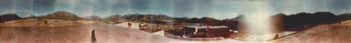 |
| 360 degree panorama from multiple images taken with 50 mm lens © Copyright 1976, 1998 Jeffrey R. Charles, All Rights Reserved. |
After the film was developed, I set up the easel and sketched some of the projected images. As had been shown in the calculations, the easel had to be tilted over 45 degrees to get the correct curvature, wedge, and image proportions when printing with a 28 mm lens. The easel tilt resulted in a 1.97x vertical exaggeration of features just below the horizon. This was close to what I wanted because tilting the image would compress the proportion of objects at the north and sough by almost the same degree. The top of each picture was enlarged 1.70x and the bottom was enlarged 3.95x. I made some improvements to the easel, made black and white test prints to refine the easel orientation, then taped the easel to the enlarger baseboard. The process was very sensitive to easel position and the proper centering and alignment of the negative in the carrier, so I made an index tracing for the projection of each negative. These index strips would also be useful in repositioning the easel should it be accidentally moved.
At last, I was ready to make my first color test print! As I had expected, variation in exposure time between the top and bottom of the paper caused a significant color shift. By trial and error, this was compensated for by registering the proper stepped series of color filters to the linear dodging mask. After the filters were added, the color paper required a different dodging ratio, which in turn changed the filtration requirements again. As full days of work on the project slipped by, this and other frustrating problems were gradually worked out. The final prints would require only two seconds of exposure on the top and a full minute on the bottom. The dodging mask had to be slid by hand over a nonlinear graduated scale I had made for the top of the easel. If I did not move the mask smoothly, the prints would have sudden and unsightly changes in density. I really wanted to have a gadget like the adjustable wind up reading masks they have in some schools. This would have assisted in obtaining smooth dodging.
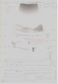 |
 |
| My first black and white test print, made on a curved and tilted conical section easel. The varying density in this print shows the considerable amount of dodging that was required to compensate for the vertical linear gradient which resulted from the extreme tilt of the easel. When the entire panorama is incrementally printed on a properly curved ant tilted easel, a flat circular image of the entire 360 degree panorama results. The same method is also applicable to incrementally converting a circular panoramic image into a straight one. | One of my first color test prints, made on the same easel as the previous black and white picture. The horizontal lines are from uneven motion of the dodging mask. The top of the print was exposed for only two seconds, while the bottom required an exposure of about one minute. These extremes in exposure required active filtration in order to compensate for the color shift which occurs in color photo paper when it is exposed for varying amounts of time. |
Finally, I was ready to make a full set of prints. In order for them to match, I had to quickly expose adjacent prints and process as many of them as possible in the same batch. In my sleep deprived state, I decided to print each picture on an individual four by five inch sheet of paper, then tape them together and process them in a Unidrum. This was a bad idea because the processing chemistry caused some of the tape to let go, resulting in uneven processing and unsightly marks from trapped chemistry. While the first prints were spoiled by things that happen when one goes for days without adequate sleep, they matched except for the flare on three pictures which was caused by shooting into the sunrise. The older 50 mm Elmar lens I had used did not have very good AR coatings, so the flare was bad.
In making the second set of prints, I exposed opposite ends of four by 10 inch sheets of paper, which fit into the processing drum without the need for tape. This set of prints was good except for the same lens flare problem that plagued the first set. I had to make several prints of these flared pictures and develop more complex dodging techniques to help bring out the detail. Unfortunately, the contrast on these few shots was just too low, so I ultimately had to settle for what I could get. Next came the painstaking task of cutting and mounting the pictures. It was a tedious process, but the final flat image was tack sharp and matched almost perfectly!
The remaining tasks were to copy the tilted circular composite image in order to make it into an oval, then make a transparency. I was not able to adequately retouch the lines between each picture on the original, so the final transparency would have to be large enough to retouch. This meant making an 8x10 transparency from the copy negative. Another process I had never done before! (The deadline did not allow time for either the copy negative or the transparency to be commercially processed).
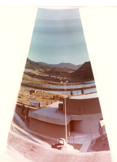
Obtaining a high resolution copy of the picture was another problem. In order to get a sharp final image, I had to copy the composite print with a large format camera. Unfortunately, I did not have a long focal length lens for my view camera, so I had to cylindrically warp the print in order to compensate for some of the perspective. This made the center of some of the individual print wedges to repeatedly pop up from their mounting, which locally canceled out some of the curvature I had worked so hard to achieve, but at least I finally had a copy negative. If I had it to do again, I would have just taken my lumps in regard to resolution and copied the tilted but flat print from a distance with a 200 mm or longer lens on a 35 mm camera, as was done for the image shown below. I did not think of this at the time - I was too sleep deprived! By the time I finished developing the copy negative, I had set my all time record of 79 continuous hours without sleep: from 8:30 on Sunday Morning to 3:30 on Wednesday afternoon! The Friday morning deadline was less than 44 hours away, but now, I had to get some sleep.
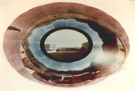 |
Now came the transparency. At about 2:00 a.m. on Thursday, I began making the first test transparency from the copy negative. By late evening, I had a good transparency. Now came the retouching. The new publisher deadline had not allowed the time to go out of town and get the correct retouching materials, so I had to use what I had. Most of my retouching materials were dyes, and they appeared to be far too dark when applied to a test transparency. They did not take well to dilution either, so I had to resort to retouching some areas with small small dots, like those in a halftone. Even worse, the dyes were subject to smearing by rubbing or with any type of moisture. This made the "pointillism" retouching vulnerable, so I had to write a note, warning the publisher against trying to clean the transparency.
Unfortunately, I had not been able to see sharply all day due to accumulated sleep deprivation and the resulting uncontrollable eye watering, and my sight became even worse throughout the day. This made it hard to see what I was doing, and resulted in a very poor retouching job. To make matters worse, the publisher apparently tried to clean the transparency incorrectly in spite of my warning, and this added numerous smears around my retouching. They also printed the picture far too light, which made the smeared retouching look even worse. I was really bummed about the quality of the published image, but that had to be that, given the time constraints. At least the end result shows what an oval 360 degree panorama looks like. Such a picture was a rarity for a small town in the mid 1970's!
Return to local table of contents
Using translating or rotating easels and exposing through a slit
After the labor intensive experience of making the above panoramic conversion, I began to think about better ways of doing it. One of the first things that came to mind was the concept of exposing the print or film through wedge shaped slit. In the case of converting a straight panorama to a circle, the panoramic negative would be translated across the negative carrier while the paper or film was rotated behind the slit. In the case of converting a circular panorama to a straight one, the original is rotated while the paper or film is translated. In the latter case, different slit and easel configurations can be more effectively used to vary the proportions of the image. For example, the vertical scale can be locally modified by cylindrically warping the paper or film.
Return to local table of contents
After seeing the final circular image I had made for the school, I wanted to obtain similar images of other subjects. When viewed through a magnifier, the high resolution image was actually reminiscent of being at the site where the panorama was taken. I really liked the fact that the image was continuous! I took several 360 degree panoramas of mountain scenes with the intention of converting them later, but never could bring myself to repeat the arduous printing procedure to convert them or build the slit based panoramic conversion device. I settled for wrapping the panoramas into cylinders, even modeling things like lamp shades from them. I soon envisioned ways to optically view localized areas of circular panoramic prints and transparencies which would correct for the curvature of the horizon.
Having all of these concepts in mind obviously made me want to have an easier way of acquiring panoramic images, especially circular ones. After some thought, I invented the two reflection axial strut reflector mentioned earlier in this paper. My conception of the axial strut and other unique wide angle reflector features is covered more in another of my papers, entitled: "All-Sky Reflector with "Invisible" Axial Camera Support".
Today, digital image processing can be used to convert panoramic images from straight to circular or oval or vice versa with relative ease. Appropriately registered spherical, cylindrical, distort, and other routines can be used to convert a panorama in short order. Additional software can be used in conjunction with popular image processing software to essentially automate the process.
Many of the complex digital image processing tasks now performed with modern software can be done, and have been done, in an old fashioned darkroom. The darkroom still has its place, but one would be crazy to manually perform something like a complex panoramic conversion in a darkroom today! Too bad I did not have access to today's digital image processing resources in 1976! This was years before Photoshop, or even P.C's for that matter!
| Example of a Digitally Converted Panorama |
 |
Appearance of the original rectangular panorama. Rather than scanning all of the original negatives, Adobe Photoshop was used to convert the previous oval image back into its original rectangular form. The darkroom process had taken days, but the digital conversion required only a few minutes. This required only a few simple steps:
|
Have special wide angle imaging needs? Versacorp offers wide angle optical instrumentation as well as consulting engineering services. For more information, see the Versacorp Web Page.
Return to local table of contents
References to my own prior art:
* U.S. Patent D312,263. "Wide Angle Reflector Attachment for a Camera or Similar Article" Filed in 1987, Issued Nov. 1990. This patent is primarily for IMPROVEMENTS over my own prototypes (i.e. the patent covers embodiments that are more desirable for commercial use than my original prototypes would be, and deals with said prototypes as prior art.) Even though this is a design patent, it covers two embodiments of the invention, giving it broad coverage since any combination of the features shown in the two embodiments would be "obvious to those skilled in the art".
* Sky and Telescope magazine, August 1986, page 186. This reference shows the first prototypes for both of my wide angle reflector designs. These prototypes were both made from simple everyday materials. The common aspect between both versions is the use of a thin AXIAL STRUT to support the camera and/or the reflector.
* Astronomy Magazine, April 1987, page 64-70, (Particularly pages 68 and 69.), Article: How to Build and Use an All-Sky Camera. This article only shows the version of my invention with the camera on top, but the original draft I sent the publisher included a lot more information, including some of the concepts presented in this paper and drawings and descriptions of other wide angle reflector embodiments. Since this particular article was about photographing the sky instead of the horizon, most of the concepts in this paper were omitted; however, the following brief paraphrased reference to the concept of my first prototype was included on page 66: "Yet another possibility (for an all-sky reflector design) is an "inside-out Cassegrain" all-sky camera. The camera goes behind the convex mirror and looks through a plastic window. A spacer rod is installed between the center of the window and the middle of a flat secondary mirror. This design is not only free from obscuration from support rods but is also very compact. It is admittedly the most difficult type to construct and also suffers from a bigger central obstruction than the others."
* Proceedings of the 1998 Riverside Telescope Makers Conference, page 74. Portable All-Sky Reflector with "Invisible" Camera Support. There were over 600 people in attendance when I presented this paper in 1987. This paper shows and describes both constructed versions of my wide angle reflector.
* A copy of my paper from the 1988 conference proceedings appears (sans images but with some updates) at my www.versacorp.com web page. Its URL is: http://www.versacorp.com/vlink/jcart/allsky.htm
* "Wide Angle Eclipse Photography Techniques" a paper at the www.eclipsechaser.com web site. Images of my prototype reflectors are shown near the beginning of this article. Various parts of the paper were written between 1986 and the present time.
* Unusual Telescopes (A book by Pete Manly) page number unknown. A photo of the first amateur version of my axial strut wide angle reflector invention (made in 1977 with a L'eggs "Sheer Energy" hose egg) is in this book. There are errors about the conception of the invention in the book. It incorrectly attributes the invention to two people. I told and wrote the author about this error after he showed me his draft, but he did not correct it before publication.
* I applied some of my wide angle reflector concepts to other disciplines while a systems engineer at the Jet Propulsion Laboratory. Most of this work is published in obscure JPL/NASA publications. The future graphics for the "ALAT" paper now at my web site will contain scans of this material.
* Whispering Pine 1977 (1977 Estes Park High School Yearbook), photo on End Sheet. 360 degree panorama which was converted to an ultra wide annular panoramic photo in the darkroom. Techniques used to produce this image are the basis for the present paper. The difficulty of this process is why I invented my first axial strut wide angle reflector in 1977.
© Copyright 1975-1997 Jeffrey R. Charles. All Rights Reserved. This document and all associated concepts, data, designs, images, techniques, trade names, and other elements are the property of Jeffrey R. Charles. All content is protected by intellectual property laws. Any form of reproduction or posting of any part of any associated document at web sites other than eclipsechaser.com, eclipsemovie.com, or versacorp.com, or any commercial use (such as in a seminar, product, program, publication, or motion picture) of data or other material in this web page, or of related material by the same author (whether said material was obtained directly or indirectly) without including this notice and without the prior express written consent of Jeffrey R. Charles is strictly prohibited. Any use other than for private, non-commercial purposes is strictly prohibited. Use of this material is subject certain Terms and Conditions. In downloading material from this web page or transferring said material from a cache, you are deemed to have agreed to these terms and conditions. For information about the licensing and/or purchase of images and/or articles or related book, movie, or technology rights, please contact Jeffrey R. Charles.
Versacorp may later publish more detailed Photoshop compatible procedures analogous to the described darkroom techniques for the horizontal to circular (and vice versa) panoramic conversion (Patent Pending) which were developed and implemented by Jeffrey R. Charles in the 1970's. Individual programmers may freely write macros based on this panoramic conversion material for their own private noncommercial use, so long as they do not exclude others from doing the same and so long as they prominently indicate the author and source of this data as well as the patent pending notice in their software. If marketed, the resulting software must be placed in the public domain or distributed as share ware for a nominal voluntary fee.
Mr. Charles has developed image processing techniques (Patent Pending) based in part on the techniques herein which are envisioned to be included in a future Versacorp software product. Those interested in commercially licensing Mr. Charles' technology are invited to direct their inquiries to licensing@versacorp.com.
Have special wide angle imaging needs? Versacorp offers wide angle optical instrumentation as well as consulting engineering services. For more information, see the Versacorp Web Page.
Return to local table of contents
Document Originated as HTML: 9 March, 1997
Text First Modified: 4 May, 1997
Test Last Modified: 24 March, 1998